Technical Issues -
Designs on Multiple Substrates II
Continuation
of Design on Multiple Substrates I
See also
Wedge Mode Massive Layers
Consider a design with 0.02%
transmittance. The same stack is deposited on the second parallel surface
of a nonabsorbing substrate. The total transmittance is 0.01% instead of
0.0004%. This is correct and the result of multiple internal incoherent reflections
between massive surfaces. A
way to increase blocking is to substitute wedge for parallel. In
that way, energy walks off the assembly. While examples below refer to coatings on a single substrate,
it applies equally to assemblies with multiple substrates.
DESIGN 2.61.3101 added Side 2 mode
FWD Wedge. The mode applies only to
designs with massive layers and is otherwise disabled. Prior to DESIGN 2.61.4517 Option 6 was enabled but
equivalent to Option 1 when no massive layers.
By eliminating reflections from secondary surfaces, a wedged
substrate increases blocking of filters containing coatings on
multiple surfaces. Another method is to utilize a slightly
absorbing substrate. |
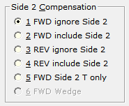 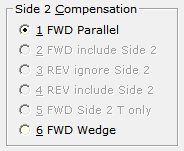
Image at right: design with massive layers |
Wedge mode assumes there are no reflections between massive surfaces.
Reflectance is the reflectance of the first surface only while
transmittance is the product of each element. When activated
Wedge is displayed
in the status bar. In actual practice, the
wedge angle must be sufficient for reflections to walk off he
assembly.
| Note: FWD Wedge
is not the same as FWD Side 2 T only
wherein %T is measured through the optic while %R is
measured with its uncoated surface treated to eliminate
reflection. |
As example we consider the IR bandpass Fnum.faw
design (included in the FilmStar installation) centered at 1640 nm. A second
(Side 2) design is centered at 1630 nm. We set k = 0.0001 for both L and H
materials.
Wedge mode is equivalent to multiplying two separate filters in
FWD ignore Side 2 mode. Reflectance is Side 1 reflectance (R1) while
transmittance is given by T1*T2. The Side 2 calculation sets substrate thickness
to zero; otherwise substrate absorption would be counted twice. Example: Download
Fnum-Diab.faw (Side 1),
Fnum-1630.faw (Side 2)
and run BASIC program
TwoSideWedge.bas. Finally open
Fnum-Diab-1630-1640.faw and evaluate in Side 2 mode 1 (Parallel) and
mode 6 (Wedge). As seen in the plot below, Both Sides and Wedge
traces overlap as expected.
TwoSideWedge.bas provides an alternative for users who do not need to
simultaneously design coatings on both sides. Want to test absorption in the
substrate (massive layer)? Set SUB k = 0.00001 in Fnum-Diab.faw and Fnum-1630.faw. Set
massive material G k =
0.00001 in Fnum-Diab-1630-1640.faw and regenerate the curves shown below.
Not sure what a massive layer is? No idea how to run a BASIC
program? Contact FTG Software for an explanation via ZOOM. When substrate k>0 the
BASIC program requires DESIGN 2.61.3058 or newer. (Contact FTG for a
workaround.)
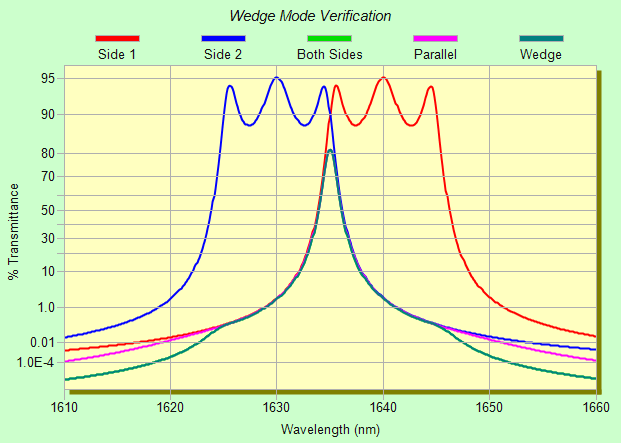
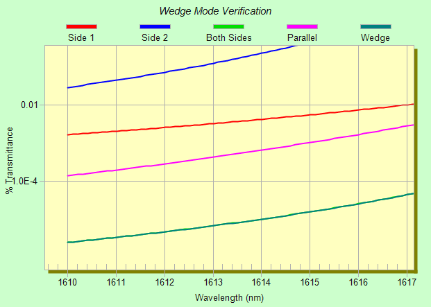
The
green Both Sides plot is covered by the
teal Wedge plot.
Using FSPlot zoom (see below) we find that blocking is improved by a factor ~200. If you try the suggested exercise (substrate k = 0.00001) you will
note much less improvement because blocking is already increased by the
absorbing substrate.
|